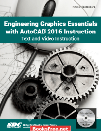
| Book Name: | Engineering Graphics Essentials with AutoCAD 2016 Instruction by Kirstie Plantenberg |
| Free Download: | Available |
| Guide Particulars : | |
|---|---|
| Language | English |
| Pages | 99 |
| Format | |
| Dimension | 7.0 MB |
Engineering Graphics Essentials with AutoCAD 2016 Instruction by Kirstie Plantenberg
In Chapter 2 you’ll be taught the significance of engineering graphics and methods to create an orthographic projection. An orthographic projection describes the form of an object. It’s a two dimensional illustration of a 3 dimensional object. Totally different line sorts are used to point seen, hidden and symmetry traces. By the top of this chapter, it is possible for you to to create a technically right orthographic projection utilizing correct projection strategies.
In Chapter 2 you’ll be taught the significance of engineering graphics and methods to create an orthographic projection. An orthographic projection describes the form of an object. It’s a two dimensional illustration of a 3 dimensional object. Totally different line sorts are used to point seen, hidden and symmetry traces. By the top of this chapter, it is possible for you to to create a technically right orthographic projection utilizing correct projection strategies.
An orthographic projection allows us to symbolize a 3-D object in 2-D (see Determine 2.2-1). An orthographic projection is a system of drawings that symbolize completely different sides of an object. These drawings are shaped by projecting the sides of the thing perpendicular to the specified planes of projection. Orthographic projections permit us to symbolize the form of an object utilizing 2 or extra views.
These views collectively with dimensions and notes are adequate to fabricate the half. When establishing an orthographic projection, we have to embrace sufficient views to utterly describe the true form of the half. The extra advanced a component, the extra views are wanted to explain it utterly. Most objects require three views to utterly describe them.
The usual views utilized in an orthographic projection are the entrance, prime, and proper aspect views. The opposite views (backside, rear, left aspect) are omitted since they normally don’t add any new info. It’s not all the time needed to make use of the three normal views. Some objects might be utterly described in a single or two views. For instance, a sphere solely requires one view, and a block solely requires two views. The entrance view reveals essentially the most options or traits of the thing. It normally comprises the least variety of hidden traces.
The exception to this rule is when the thing has a predefined or typically accepted entrance view. All different views are based mostly on the orientation chosen for the entrance view. The highest, entrance, and backside views are all aligned vertically and share the identical width dimension. The left aspect, entrance, proper aspect, and rear views are all aligned horizontally and share the identical peak dimension (see the determine proven in Train 2.3-1).
Download Engineering Graphics Essentials with AutoCAD 2016 Instruction by Kirstie Plantenberg PDF free
Related Results : engineering graphics essentials with autocad 2019,engineering graphics essentials with autocad 2020 instruction,engineering graphics essentials with autocad 2020 instruction pdf,engineering graphics essentials with autocad 2021,engineering graphics essentials with autocad 2021 answer keyengineering graphics essentials with autocad 2021 instruction,




![[PDF] Draw Buildings and Cities in 15 Minutes Draw Buildings and Cities in 15 Minutes pdf](https://www.freepdfbook.com/wp-content/uploads/2021/06/Draw-Buildings-and-Cities-in-15-Minutes-218x150.jpg)




![[PDF] Digital Image Processing An Algorithmic Introduction Using Java Digital Image Processing An Algorithmic Introduction Using Java](https://www.freepdfbook.com/wp-content/uploads/2022/06/Digital-Image-Processing-An-Algorithmic-Introduction-Using-Java.jpg)


![[PDF] 43 Years JEE ADVANCED + JEE MAIN Chapterwise & Topicwise Solved Papers 43 Years JEE ADVANCED (1978-2020) + JEE MAIN Chapterwise & Topicwise Solved Papers Physics PDF](https://www.freepdfbook.com/wp-content/uploads/2022/03/43-Years-JEE-ADVANCED-1978-2020.jpg)

![[PDF] Problems in Physical Chemistry for JEE (Main & Advanced) Problems in Physical Chemistry for JEE (Main & Advanced) Free PDF Book Download](https://www.freepdfbook.com/wp-content/uploads/2022/03/Problems-in-Physical-Chemistry-for-JEE-Main-Advanced.jpg)
![[PDF] Engineering Physics (McGraw Hill)](https://www.freepdfbook.com/wp-content/uploads/2021/05/bafc8c2685bb6823a9c56134f7fba5df.jpeg)
![[PDF] Engineering Chemistry By Shashi Chawla](https://www.freepdfbook.com/wp-content/uploads/2022/05/Theory-And-Practicals-of-Engineering-Chemistry-By-Shashi-Chawla-free-pdf-book.jpeg)
![[PDF] Chemistry: An Introduction to Organic, Inorganic & Physical Chemistry Chemistry: An Introduction to Organic, Inorganic & Physical Chemistry](https://www.freepdfbook.com/wp-content/uploads/2022/04/Chemistry-An-Introduction-to-Organic-Inorganic-Physical-Chemistry.jpg)
![[PDF] Essentials of Physical Chemistry Essentials of Physical Chemistry Free PDF Book by Bahl](https://www.freepdfbook.com/wp-content/uploads/2022/04/Essentials-of-Physical-Chemistry-bahl.jpg)
![[PDF] Biological control of plant-parasitic nematodes: soil ecosystem management in sustainable agriculture Biological control of plant-parasitic nematodes: soil ecosystem management in sustainable agriculture](https://www.freepdfbook.com/wp-content/uploads/2022/05/Biological-control-of-plant-parasitic-nematodes-soil-ecosystem-management-in-sustainable-agriculture.jpg)
![[PDF] Human Anatomy: Color Atlas and Textbook Human Anatomy: Color Atlas and Textbook Free PDF Book](https://www.freepdfbook.com/wp-content/uploads/2022/05/Human-Anatomy-Color-Atlas-and-Textbook.jpg)
![[PDF] Concepts of Biology Book [Free Download]](https://www.freepdfbook.com/wp-content/uploads/2022/05/Concepts-of-Biology.jpg)
![[PDF] Essentials of Biology [Free Download] Essentials of Biology Free PDF BOok Download](https://www.freepdfbook.com/wp-content/uploads/2022/05/Essentials-of-Biology-Free-PDF-Book-Downlaod.jpg)
![[PDF] Human Biology Book [Free Download]](https://www.freepdfbook.com/wp-content/uploads/2022/05/PDF-Human-Biology-Book-Free-Download.jpg)
